1. Project Overview

|
The idea for this project is to create a sixty second timer using the PLD Mode in MultiSim. The one's place is controlled by a newly acquired knowledge, being the synchronous 74LS163 MSI counter. The ten's place is controlled by asynchronous group of four SSI logic gates (J/K). Lastly, each display will use a 74LS48 BCD-To-Seven-Segment display driver, which can be found in the Design Mode. The displays should be able to count from 00 to 59, symbolizing the zero to sixty seconds.

|
2. PLD Circuit
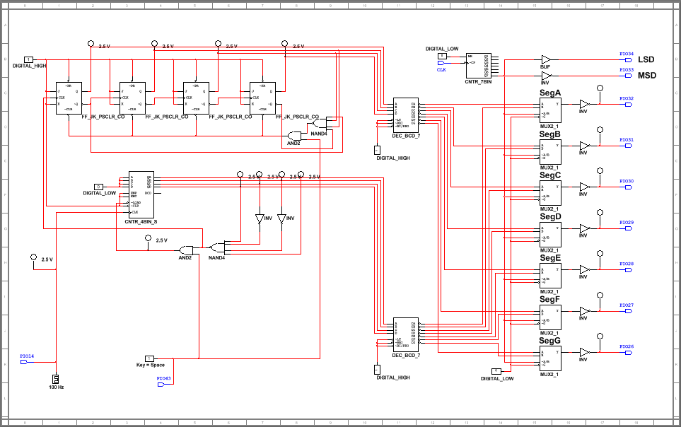
The circuit above was designed in the PLD Mode of MultiSim and downloaded onto a PLTW breadboard.
3. Final Project Conclusions
In conclusion, the circuit I created had a combined use of synchronous and asynchronous counters. The difference between the two is that synchronous counters are simultaneously clocked, much faster, and take more logic than the asynchronous counters. Another key difference is that the synchronous counters do not experience the "ripple effect" where the sequence overlaps and "hiccups" because of the delay in each of the flip-flop's rising or falling action. In the previous week, my class has learned about both the 74LS163 and 74LS193 MSI logic gates. There are a few differences between the two, including the synchronous and asynchronous Load and Clear respectively. Also, the '163 is the only gate that will show the last binary entered into the Load input. Lastly, the '193 counts both up and down whereas the '163 only counts up.
Once the clock starts, the '163 counter counts up from zero to nine in the one's place, reading and showing the binary 1001 then cycling back down to zero. The SSI J/K Flip-Flop's control the ten's place and reads the binary 1001 as the rising action of the clock to count up starting also at zero and reading the binary 0110 to end on five. This count from 00 to 59 repeats endlessly unless the Reset is grounded. This Reset is one of the inputs in the two AND gates that are connected to the Load and Clear. When its value is zero, the two digits of the number turn to 00 until it is toggled back to power and the counting starts at from the beginning. The clock should be set to 1 Hz so that the period, or change in the numbers, adds one to the previous digit every second. In the PLD Mode, there are two seven segment displays named DEC_BCD_7. These gates read the four input binary from both the one's and ten's place and sends seven outputs, one for each segment, to multiplexer A through G. There are also pins throughout the design, each having a specific job in the circuit. When this is transferred to the board, each pin has a designated input or output on the C-Mod S6 that will be connected to various regions on the board. The only two inputs are the Clock, which is pin number 14 and is connected to DIO0 on the board, and Reset, affiliated with pin number 43 and sent to S0. The seven outputs are for each displayed segment on the board. Compared to my classmates, we seem to all have the same idea through using the '163 gates. When it comes to the SSI Flip-Flops, I have added an extra bit. It isn't necessary to have the fourth Flip-Flop but does not impact the effect in the end. The Resets are connected in the same way where only one of the AND inputs need to be zero for the number to go to 00.
Once the clock starts, the '163 counter counts up from zero to nine in the one's place, reading and showing the binary 1001 then cycling back down to zero. The SSI J/K Flip-Flop's control the ten's place and reads the binary 1001 as the rising action of the clock to count up starting also at zero and reading the binary 0110 to end on five. This count from 00 to 59 repeats endlessly unless the Reset is grounded. This Reset is one of the inputs in the two AND gates that are connected to the Load and Clear. When its value is zero, the two digits of the number turn to 00 until it is toggled back to power and the counting starts at from the beginning. The clock should be set to 1 Hz so that the period, or change in the numbers, adds one to the previous digit every second. In the PLD Mode, there are two seven segment displays named DEC_BCD_7. These gates read the four input binary from both the one's and ten's place and sends seven outputs, one for each segment, to multiplexer A through G. There are also pins throughout the design, each having a specific job in the circuit. When this is transferred to the board, each pin has a designated input or output on the C-Mod S6 that will be connected to various regions on the board. The only two inputs are the Clock, which is pin number 14 and is connected to DIO0 on the board, and Reset, affiliated with pin number 43 and sent to S0. The seven outputs are for each displayed segment on the board. Compared to my classmates, we seem to all have the same idea through using the '163 gates. When it comes to the SSI Flip-Flops, I have added an extra bit. It isn't necessary to have the fourth Flip-Flop but does not impact the effect in the end. The Resets are connected in the same way where only one of the AND inputs need to be zero for the number to go to 00.
